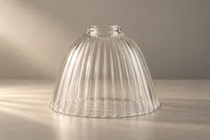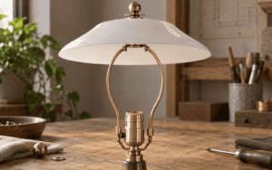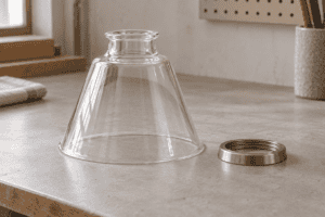
A hole in a glass lamp shade may carry the shade, locate it, give a cable a path, accept a screw, or clear part of the fixture. That makes the opening an engineered interface, not a decorative afterthought.
The useful question is not simply, "What diameter is the hole?" A supplier also needs to know where the measurement starts, which way the hole axis points through a curved wall, what hardware touches the glass, when the opening is produced, and how the finished part will be inspected. Those decisions affect the forming route, secondary processing, tooling, sample plan, and quotation.
This guide explains how to specify glass lamp shade holes and cutouts for a custom fixture. It is written for design and procurement review, not as a do-it-yourself drilling tutorial. Do not drill an installed shade or glass of unknown material and treatment. Have the manufacturer confirm whether the proposed operation is suitable for the specific glass and production sequence.
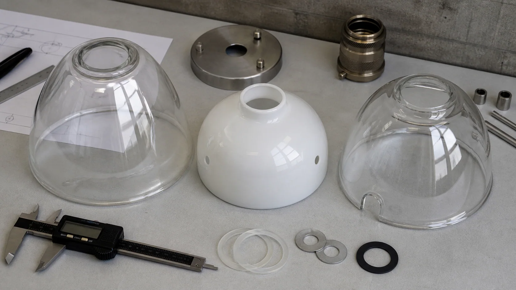
Start with the job the opening must do
An opening can look correct in a rendering and still fail during assembly. Define its function before choosing its shape or process.
| Opening function | What it interfaces with | What the buyer should control |
|---|---|---|
| Central mounting opening | Socket, threaded stem, retaining ring, cap, or canopy hardware | Finished diameter, bearing surface, concentricity, gasket and washer stack |
| Side mounting hole | Set screw, pin, clip, bracket, or standoff | Hole count, angular spacing, height, axis, screw-tip contact, local clearance |
| Cable exit | Insulated cable, strain relief, sleeve, or grommet | Minimum clear path, edge condition, bend path, assembly sequence |
| Vent or service opening | Air path, access tool, sensor, or removable fastener | Open area, location, cleaning access, appearance from normal viewing angles |
| Slot or notch | Fixed bracket, tab, cable, or anti-rotation feature | End radius, width, depth, corner condition, insertion direction |
The same nominal diameter can serve very different jobs. A center opening held between broad gaskets does not behave like a small side hole contacted by a screw. Give the supplier the complete interface rather than asking the glass to be designed around one isolated number.
Choose the opening route before fixing the drawing
Glass shade openings can be created during forming or by a later operation. The feasible route depends on glass family, wall shape, opening geometry, production quantity, surface finish, and treatment sequence. It also depends on the equipment and fixtures available to the manufacturer.
| Route | Typical reason to consider it | Decisions that still need confirmation |
|---|---|---|
| Formed or molded opening | Repeated geometry, a neck or lip, integrated mounting feature | Tooling, draft, seam position, local wall, final finishing, dimensional variation |
| Opened and finished after forming | A blown or pressed blank needs its mouth brought to final size | Cut line, grinding allowance, rim finish, final measurement surface |
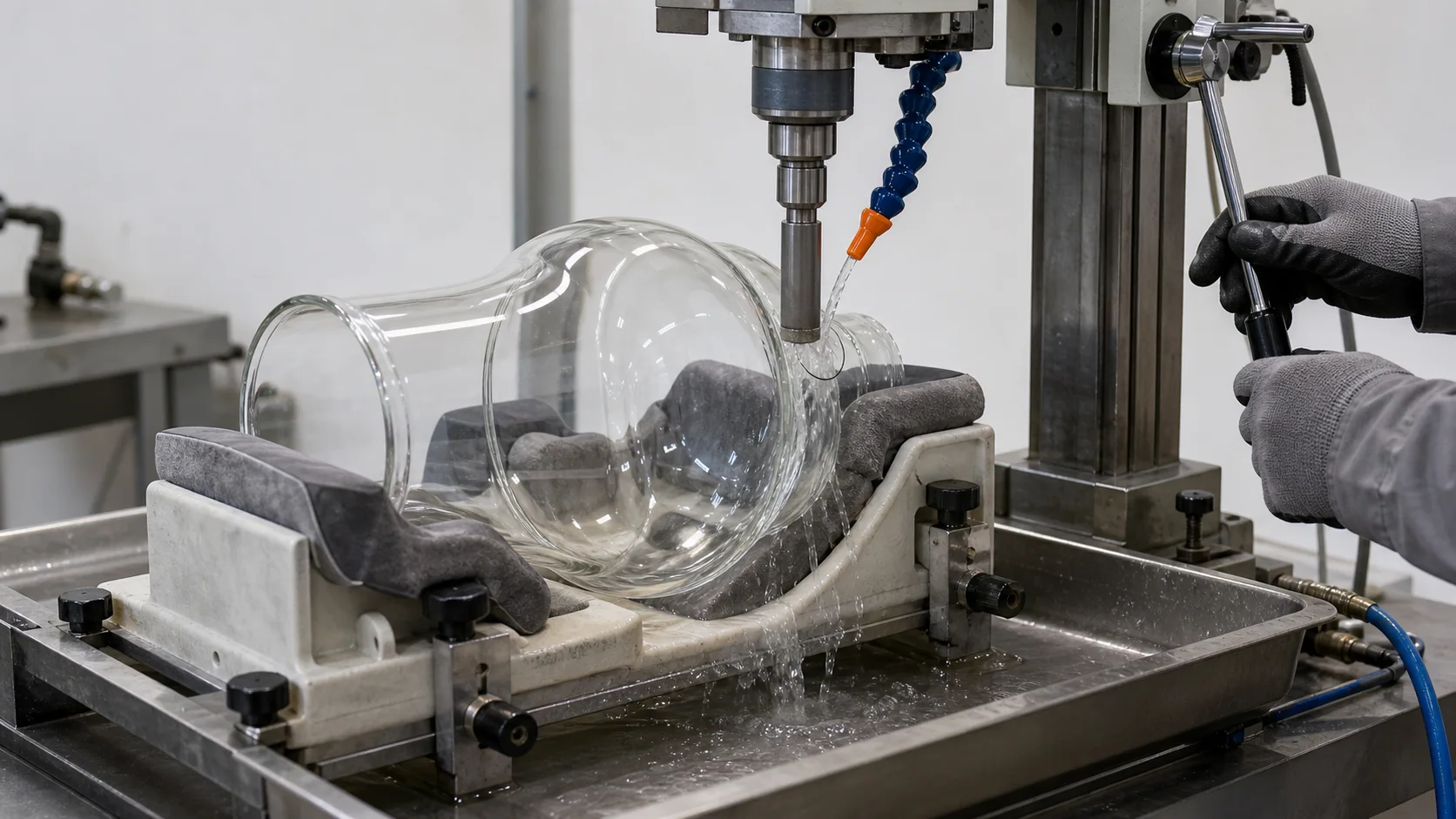
| Diamond-drilled hole | A round through-hole is needed in suitable annealed glass | Support fixture, cooling, entry and exit condition, chipping criteria, cleaning |
| Ground or machined cutout | An opening needs adjustment, a slot, or a controlled contact face | Corner radius, edge finish, tool access, local wall and process marks |
| Laser or other specialist process | Fine geometry or a process-specific production case | Glass compatibility, available machine envelope, edge quality, cost and throughput |
Corning describes laser systems that can drill holes and produce circles, slots, and other cutouts in certain strengthened and unstrengthened glass applications. That is evidence that the technology exists, not evidence that it is the right or available route for every three-dimensional lamp shade. Ask the actual supplier to identify the proposed process and its limits.
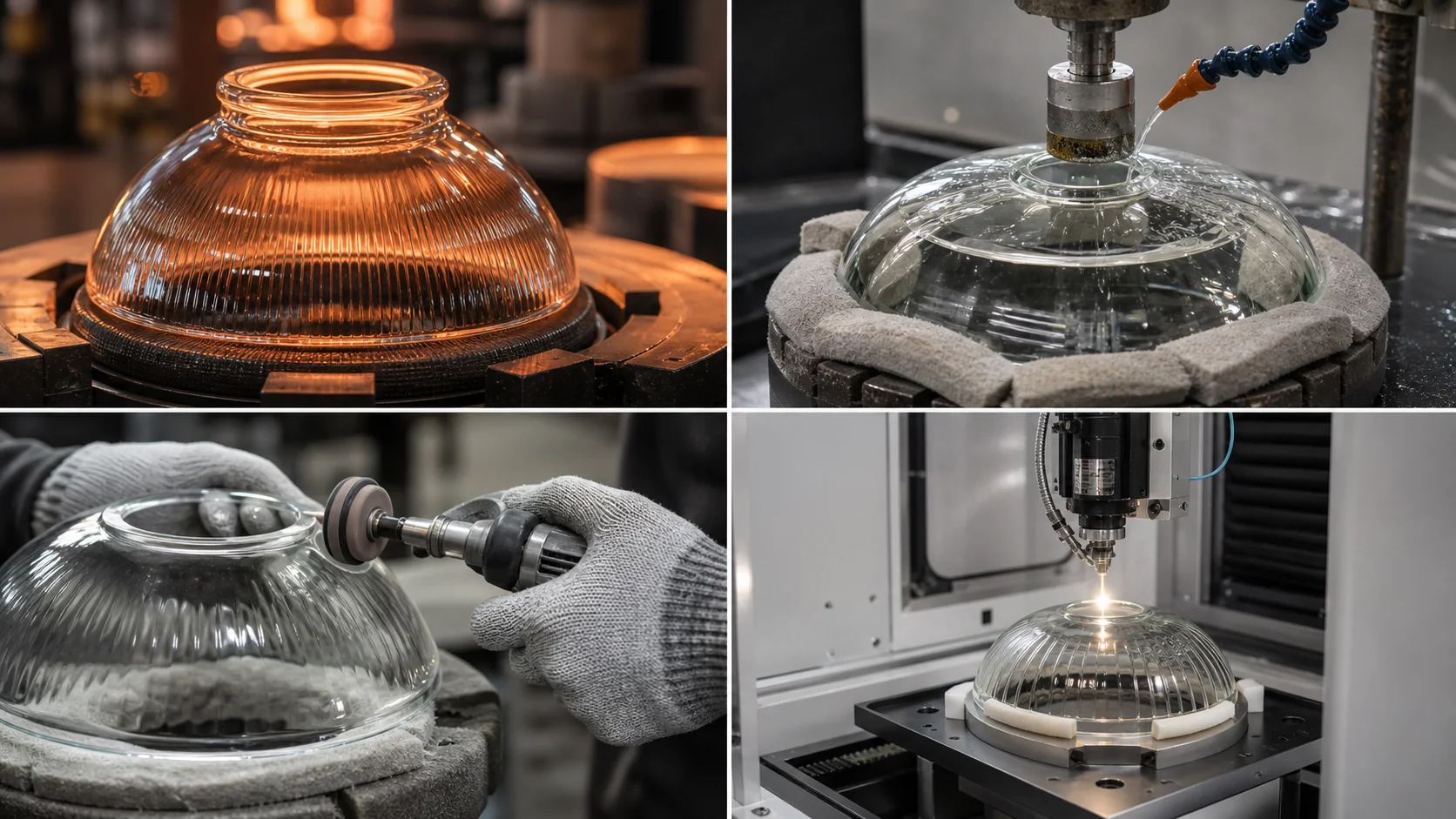
Formed openings can combine fit and shape
A formed opening may include a neck, shoulder, flange, thread-like feature, or reinforced region. It can reduce secondary work when the geometry is stable and the quantity supports tooling. It can also introduce draft, mold seams, local thickness changes, or flash that must be understood before the buyer assigns a tight finished dimension.
State whether the drawing describes the as-formed surface or a surface that will be ground afterward. If hardware bears on the opening, identify the final contact face. The mold dimension alone may not be the dimension that controls assembly.
Drilled holes depend on support and sequence
Mechanical drilling removes material from a brittle part. The workholding, tool path, cooling, wall support, and entry and exit conditions all matter. A round hole through a flat panel is not automatically equivalent to a hole through a tapered or doubly curved shade wall.
The drawing should not dictate a generic drill speed or tool merely because it appeared in a fabrication guide. Give the supplier the required result, access constraints, material, wall condition, quantity, and acceptance method. The supplier can then propose the operation and sample evidence.
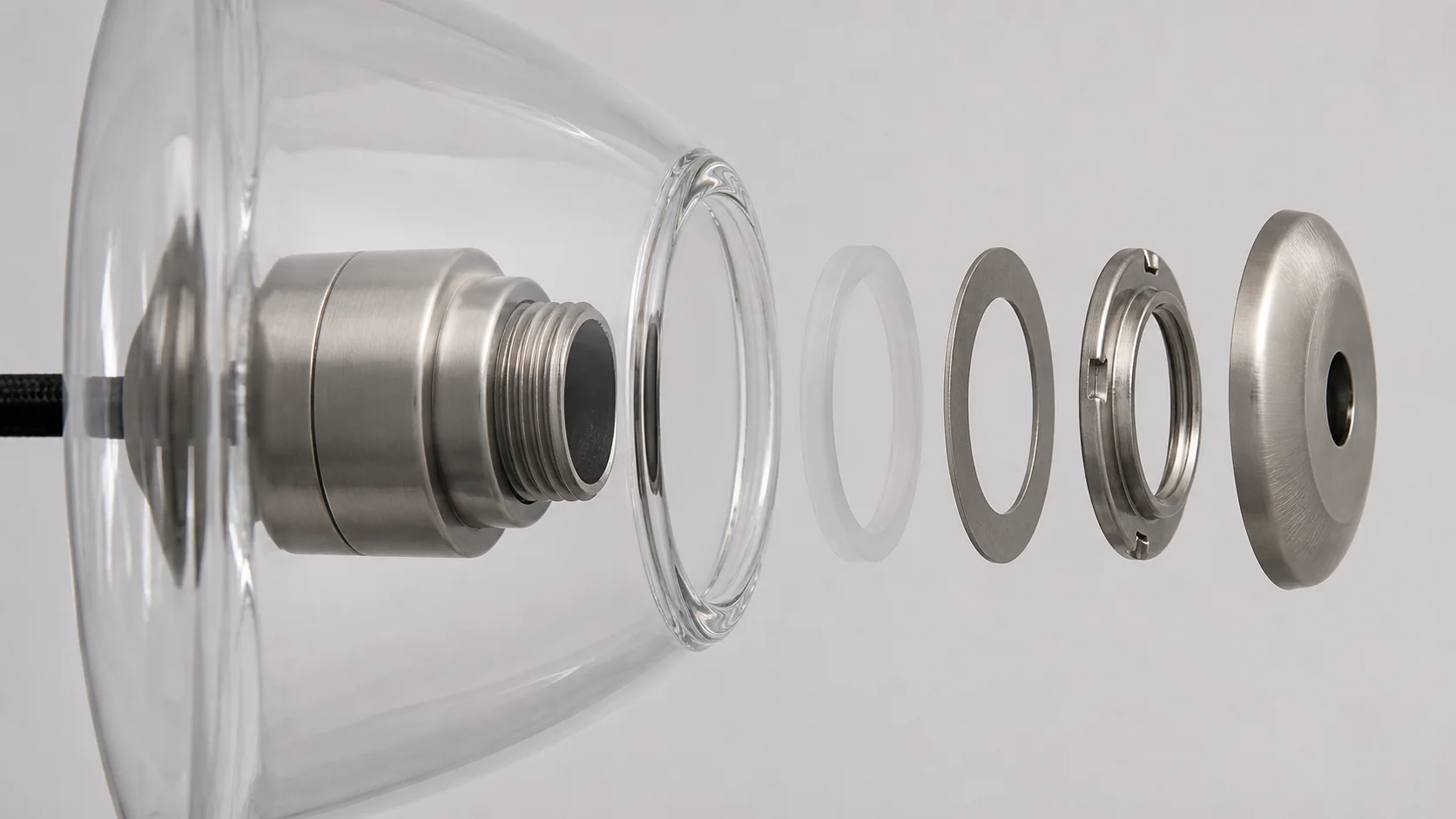
Specify central mounting openings as a complete stack
A central hole is often described as a pendant opening or lamp-holder hole. The label is useful, but the complete mounting stack determines whether the shade seats without rocking, binding, or point loading.
Include these parts in the review:
- The socket, threaded stem, or holder that passes through the opening.
- Any upper and lower gasket that cushions the glass.
- Washers, cups, caps, rings, or shoulders that spread the load.
- The nut or retaining feature and how it is tightened.
- Cable and strain-relief parts that also need clearance.
- The assembled orientation and the direction of gravity.
Define whether the controlled hole size is measured at the inner face, outer face, narrowest section, or a gauge plane. A curved wall or tapered opening may have more than one valid diameter. If a cap must hide the hole, include its usable cover diameter rather than relying on a catalog name.
Do not treat nominal socket size as a finished glass dimension. Hardware sold under the same lamp-holder designation can differ in thread, shoulder, retaining ring, gasket, and installation arrangement. Send the production hardware or a controlled drawing of it.
Locate side holes from a mounting datum
Side holes commonly accept screws, pins, spring elements, or brackets. Their position controls whether the hardware shares load evenly and whether the shade sits level.
Avoid locating a side hole from a decorative edge or an uncontrolled high point. Seat the shade on the surface that controls installation, then define a datum system. A practical drawing may use:
- datum A for the fitter contact face or mounting ring;
- datum B for the shade centerline or central axis;
- datum C for an orientation feature, seam, flat, or agreed visual reference.
From those references, specify the hole-center height, angular position, number of holes, spacing pattern, and axis direction. For opposed holes, say whether they must share one line through the shade or merely sit at equal angular spacing.
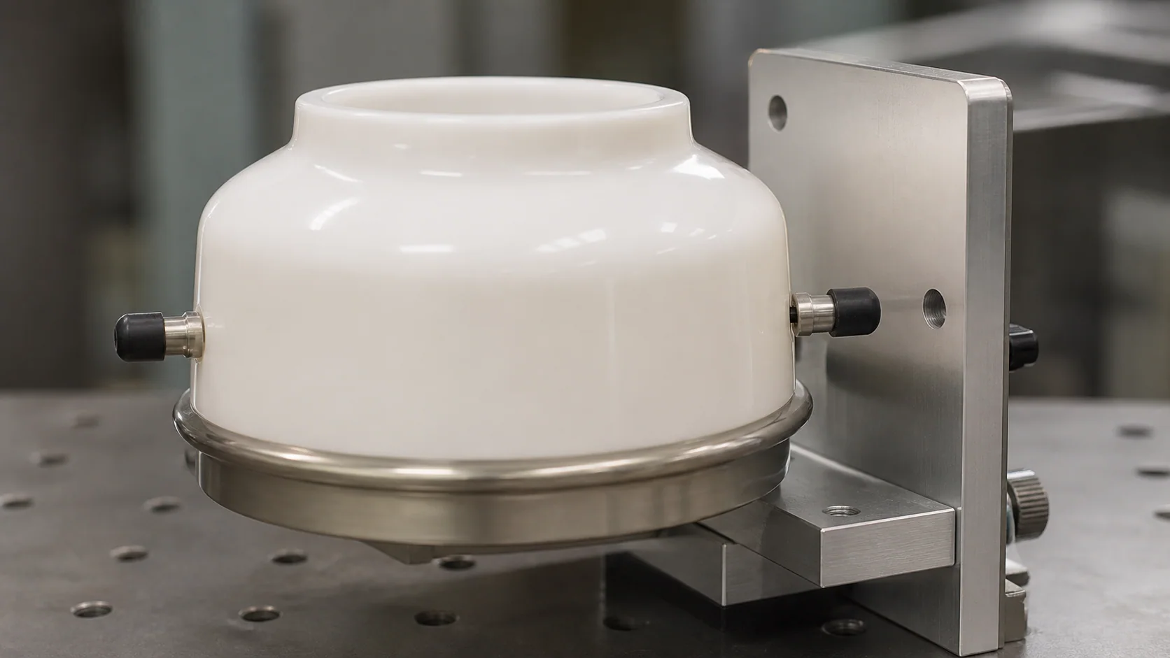
Show the screw tip and contact method
A screw-retained shade needs more than a matching hole. Show whether the screw passes through the glass, enters only partway, bears on a grommet, or contacts a metal or polymer insert. Record the intended screw-tip shape and whether the installer tightens to a hard stop or only until the shade is retained.
Do not rely on assembly force to pull a mislocated hole into position. If three screws need to flex the glass or bracket to align, the nominal dimensions are not describing a stable assembly. The sample review should use the actual fixture and normal installation sequence.
Draw slots and notches with finished corner geometry
Slots and notches can provide a cable path, clear a bracket, or allow the shade to enter a fixed assembly. They also create local geometry that is more complex than a round hole.
Define:
- the finished width and depth;
- the root or end radius;
- the opening direction;
- the relationship to the nearest rim, seam, bend, or decorative feature;
- the required edge finish;
- the mating tab, cable, or bracket envelope;
- whether the feature is visible after assembly.
A drawing that shows a sharp internal corner may be impossible or undesirable for the proposed process. Ask the supplier to return the achievable radius on the drawing before tooling or sample work. If a bracket must slide through the notch and rotate into place, show that movement with the maximum hardware envelope.
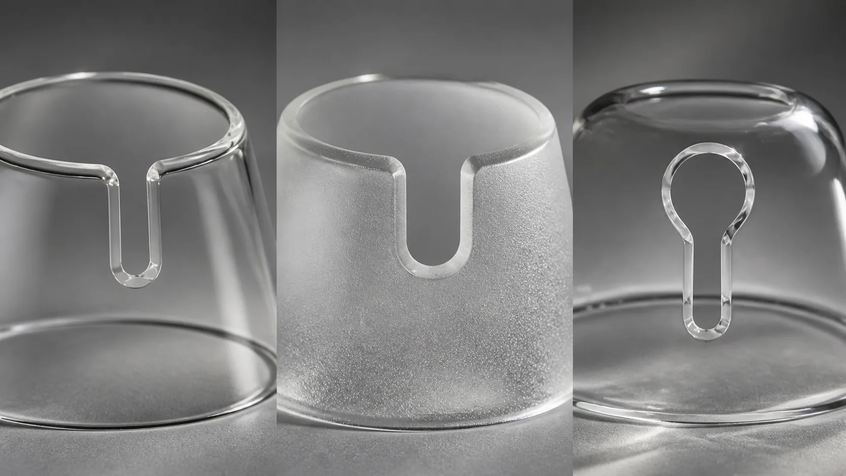
Define the hole axis through curved glass
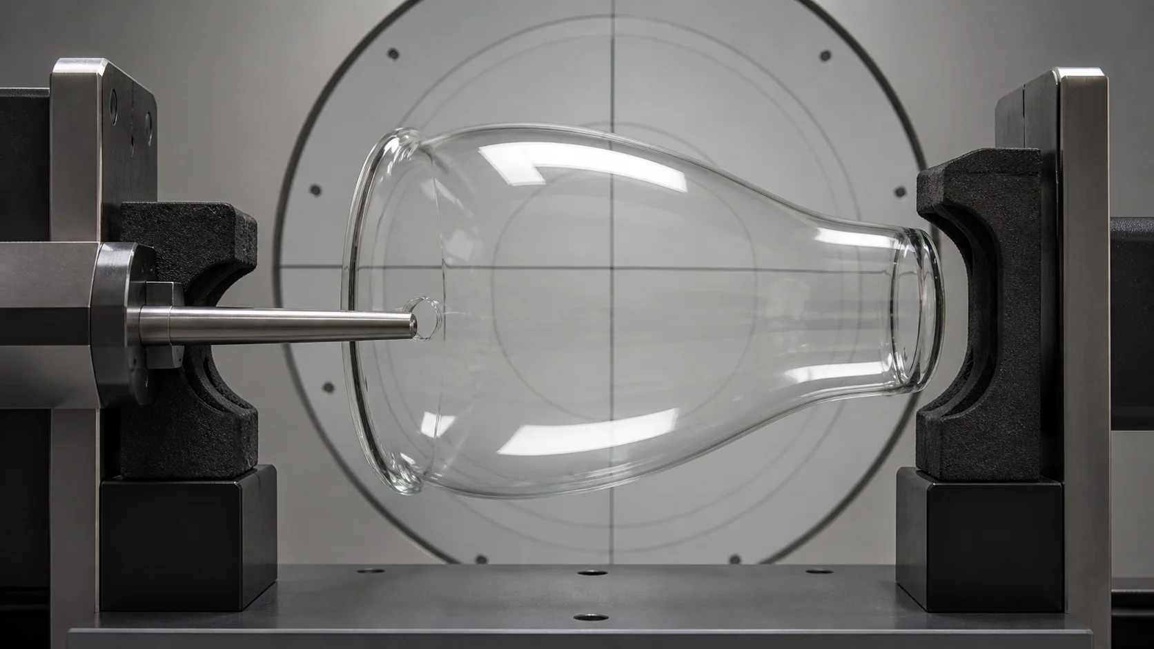
A two-dimensional front view can hide a critical ambiguity: which direction does the hole travel through the wall?
On a cylindrical shade, a radial hole usually points toward the cylinder axis. On a cone, bell, globe, or freeform shade, the local surface normal and the product centerline may not coincide. A tilted hole can change the apparent shape, usable clearance, screw alignment, and edge thickness around the opening.
Use a section view through the hole and show one of the following:
- the hole axis relative to the product centerline;
- an angle from a defined datum plane;
- a radial line to a defined construction center;
- a mating pin or screw that establishes the required direction;
- a functional gauge that represents the assembled hardware.
Also state where the hole diameter is measured. A cylindrical tool passing through an angled or curved wall can produce an opening that looks oval from one viewing direction even when the bore itself is round.
Control location without pretending the surface is flat
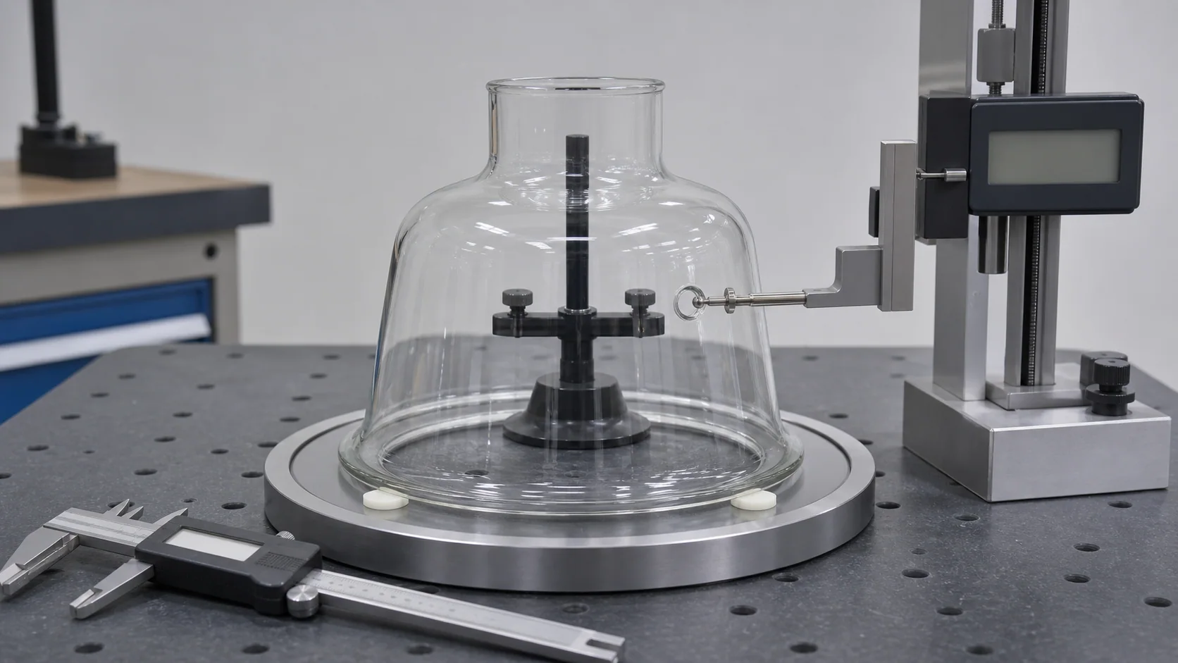
Curved parts need a repeatable measurement method. A dimension traced along the glass surface may differ from a straight chord, a projected height, or an angular measurement around the centerline. Write which one controls.
| Location method | Useful when | Risk to remove from the drawing |
|---|---|---|
| Height from seated datum | The shade has a stable mounting face | Measuring from an irregular decorative rim instead |
| Angle around centerline | Multiple holes repeat around a rotational part | No defined zero-angle orientation |
| Chord or projected distance | Inspection uses a fixture or optical view | Confusing surface distance with straight distance |
| Coordinate from fixture datums | The part has controlled orientation features | Datums cannot be reproduced on the real shade |
| Functional gauge | Hardware alignment matters more than an isolated coordinate | Gauge does not represent worst-case hardware |
The glass lamp shade technical drawing checklist explains the broader drawing package. For holes and cutouts, add a dedicated section view and inspection method rather than leaving the feature as an unqualified circle.
Treat edge distance and local wall as design questions
The material remaining around an opening affects processing, handling, and assembly. The nearest rim, another hole, a mold seam, a sharp profile change, or a thin local wall can all change what is feasible.
Do not import one minimum edge-distance ratio from architectural flat glass and present it as a universal lamp shade rule. Flat panels and curved, formed shades differ in geometry, wall variation, residual stress, support, and loading. Instead, give the supplier:
- the actual glass family and forming route under consideration;
- nominal and expected local wall condition;
- the complete hole or cutout geometry;
- distance to every nearby edge and feature;
- assembly load and contact parts;
- whether the area is visible or handled;
- required sample and production tests.
Ask the supplier to mark any risk area and proposed geometry change on the controlled drawing. A larger radius, moved hole, wider gasket, different fastener, or formed boss may solve the interface more reliably than demanding the original geometry without process review.
Put the finished hole edge in the acceptance plan
The hole edge may be concealed by a gasket, exposed to view, touched during assembly, or loaded by hardware. Define what is inspected after the final operation.
| Check | Possible inspection approach | Approval question |
|---|---|---|
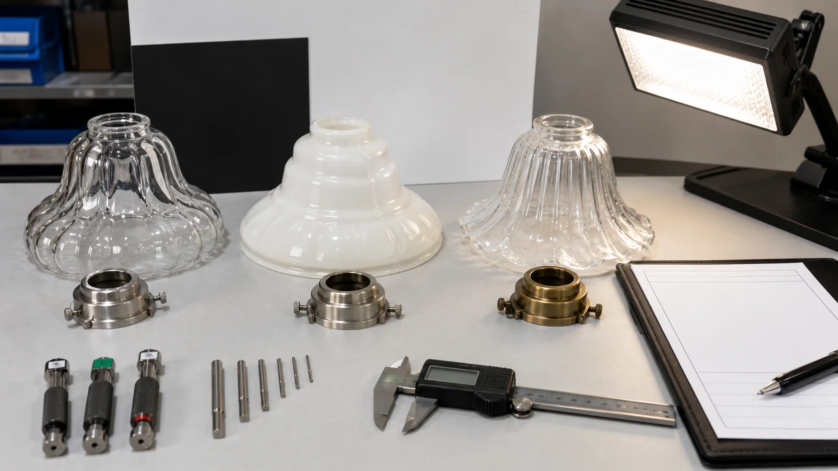
| Diameter or width | Calipers, plug gauge, pin gauge, or mating part | Which plane or section controls the result? |
| Position | Datum fixture, height gauge, optical check, or functional gauge | What datum and orientation are reproducible? |
| Axis | Pin gauge, fixture pin, or section comparison | Must the hardware pass freely or align to a target angle? |
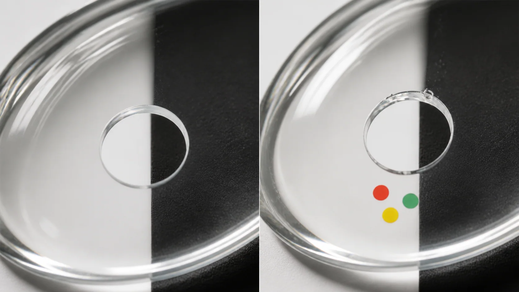
| Edge condition | Raking light, magnification, approved limit samples | Which chips, shells, grind marks, or rough areas are acceptable? |
| Local profile | Template, section gauge, or controlled scan | Has drilling or grinding changed the surrounding wall? |
| Assembly | Complete fixture hardware and normal installation method | Does the shade seat and retain without forced alignment? |
The glass lamp shade edge finishing guide explains rim terminology in more detail. A hole edge may need its own process description and acceptance sample because access, visibility, and geometry differ from an open rim.
Use limit samples carefully
A physical sample can help define cosmetic edge appearance, but identify what the sample controls. One sample may approve hole-edge appearance without approving diameter, position, material, color, or overall profile. Keep measurable dimensions on the drawing.
Photograph both faces of the opening under agreed light. If chips or grind marks are being reviewed, include scale and identify the viewing distance used for cosmetic inspection. Retain the approved record with the drawing revision.
Review the hardware stack for point loading
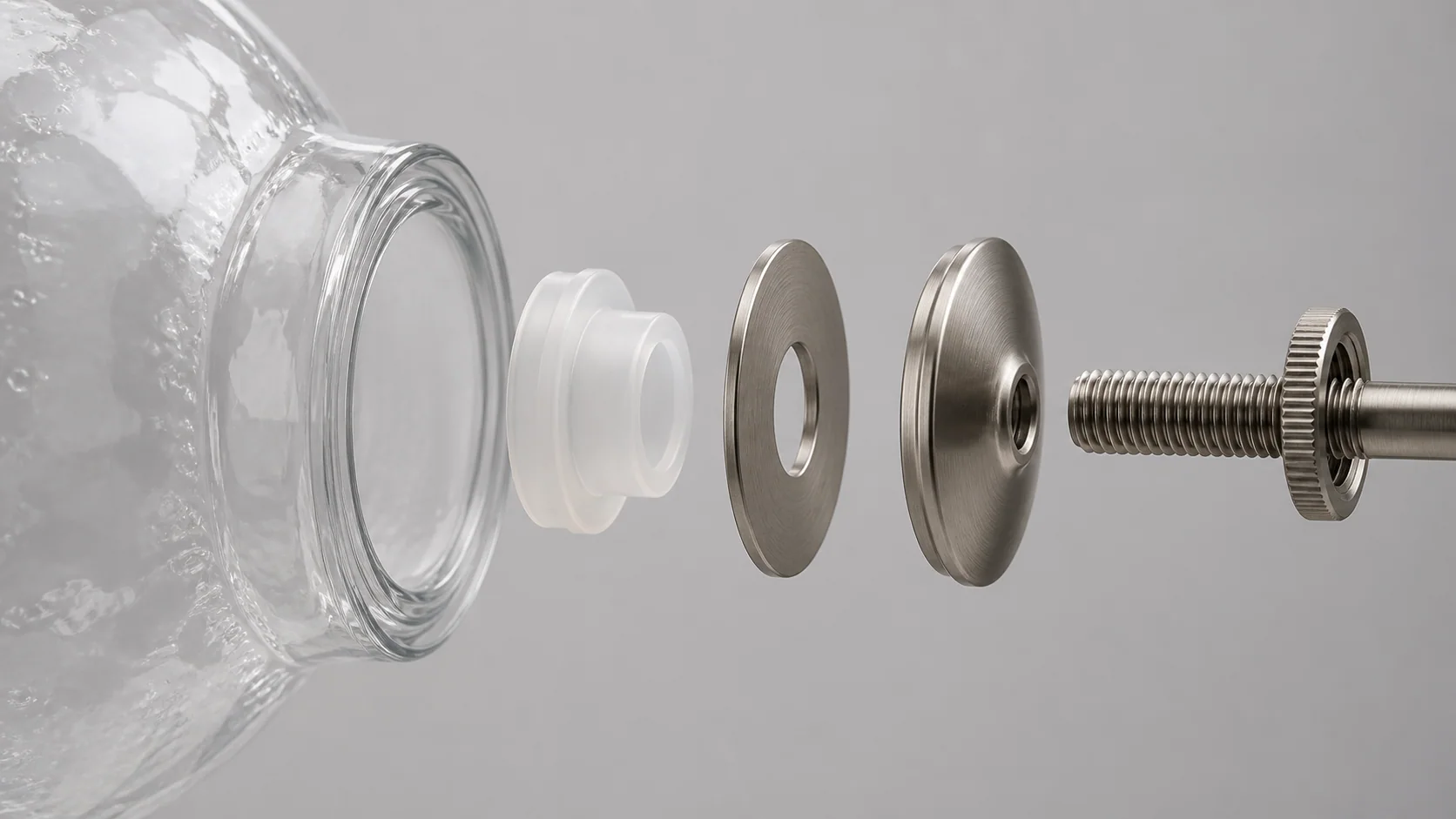
Glass should not be asked to compensate for a tilted washer, undersized gasket, sharp screw tip, burr, or uneven mounting surface. Review every contact around the opening.
Check whether:
- A gasket covers the full intended bearing area.
- A washer or cap sits flat on the actual curved surface.
- Threads, burrs, or metal corners can touch the glass.
- Tightening can continue after the hardware reaches the intended stop.
- Thermal movement can change the clamp condition.
- Cable pull or fixture movement transfers load to the hole edge.
- Service access encourages over-tightening or tool contact.
If the mounting needs a specific grommet hardness, washer profile, or tightening method, include that part in the controlled bill of materials. A sample passed with a soft temporary gasket does not validate production with a thinner or harder replacement.
Confirm drilling, finishing, and heat-treatment sequence
Ask when the opening is created relative to forming, annealing, decorative finishing, strengthening, coating, and final inspection. The order can affect access, edge quality, dimensions, and whether a later operation is possible.
Pilkington states that toughened flat glass should not be cut, sawed, drilled, or edge worked after toughening. Its process material also places required drilling before shaping and strengthening in automotive glass production. These are authoritative examples of why sequence matters, but they do not define the production route for every lamp shade.
For the actual project, ask:
- Is the part annealed, heat strengthened, thermally toughened, chemically strengthened, or untreated at the drilling stage?
- Is the opening formed before annealing or machined after annealing?
- Will grinding, polishing, coating, or cleaning change the finished size?
- Can the part be supported without distorting or marking visible surfaces?
- Which face is the tool entry and which is the exit?
- What sample quantity is needed to demonstrate repeatability?
Do not approve a material label such as "tempered" without knowing how the shade and opening are actually processed. The guide to glass lamp shade materials covers material selection; the manufacturer still needs to confirm the exact process for the proposed part.
Inspect the sample with production-intent parts
The first sample review should reproduce the actual assembly, not only a caliper measurement on an empty shade.
Use this order:
- Confirm part number, material, process route, and drawing revision.
- Seat the shade on the defined datum in its installation orientation.
- Measure the finished opening at the stated plane or with the stated gauge.
- Verify location and axis from the drawing datums.
- Inspect both opening faces and the local wall under agreed light.
- Assemble the production-intent gasket, washer, holder, screw, cable, and retaining parts.
- Check clearance, seating, alignment, and retention without forced correction.
- Record any approved deviation on a new revision or controlled approval form.
Keep an approved master only when storage and handling will preserve it. A fragile glass sample can be damaged or confused with another revision. Photos, measurements, fixture records, and a signed drawing make the decision easier to reproduce.
Common specification mistakes
Giving only a hole diameter
Diameter without location, axis, measurement plane, edge finish, and hardware context leaves the critical decisions open. Add a section and the complete mounting stack.
Locating holes from an irregular rim
A decorative or hand-finished rim may not be a stable datum. Use the mounting contact, centerline, and an orientation reference that production inspection can reproduce.
Drawing sharp internal corners in glass
A square CAD corner does not describe an achievable glass cutout. Define the functional clearance, then have the supplier return the proposed finished radius.
Treating a nominal lamp-holder size as the glass size
The socket designation does not include every retaining ring, gasket, washer, thread, and cap dimension. Send the hardware drawing or physical parts.
Approving appearance before assembly
A clean-looking opening can still be tilted, misplaced, or too tight for the production hardware. Perform the functional check before accepting the cosmetic result.
Changing hardware after the glass sample
A new washer, screw, gasket, or cap can change clearance and contact stress. Recheck the assembly when any load-bearing interface changes.
Build a quote-ready hole and cutout handoff
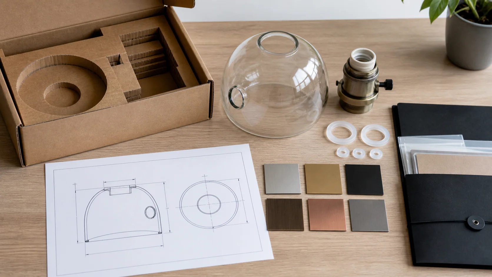
Send one controlled package with:
- shade drawing and section through every opening type;
- part number, revision, units, and intended quantity;
- glass family, finish, color, and forming route if already decided;
- finished hole, slot, or notch dimensions;
- datums, position, angular spacing, and hole-axis definition;
- local wall and nearest-edge information;
- actual fixture hardware or controlled hardware drawings;
- gasket, washer, grommet, screw, cable, and retention details;
- assembly orientation and installation sequence;
- sample inspection and production acceptance method;
- packaging protection for protruding or locally weakened areas;
- open questions that require the manufacturer's feasibility response.
Use the custom lamp shade RFQ builder to organize the project details. Attach the drawing and hardware references, then ask the supplier to return the proposed opening process, achievable geometry, inspection method, tooling requirement, sample plan, and lead time before production release.
Frequently asked questions
Can a hole be drilled in any glass lamp shade?
No. Feasibility depends on the glass composition, treatment state, wall geometry, residual stress, access, support method, hole location, and required quality. Do not drill an installed shade or unknown glass. Send the part and hardware requirements to the manufacturer for a process review.
Should a lamp shade opening be molded or drilled?
A formed or molded opening can suit repeat production and integrated neck or lip geometry. Drilling can suit certain round through-holes in a compatible formed part. Tooling, quantity, tolerance, wall condition, finish, and process sequence determine the practical choice. Ask the supplier to quote the proposed route rather than specifying one by habit.
How should a hole in a curved glass shade be measured?
Define the finished diameter or width at a stated plane, then locate the center from repeatable mounting datums. Add a section showing the hole axis through the curved wall. A plug, pin, or functional hardware gauge can remove ambiguity when calipers do not represent the real interface.
What clearance should be left around a lamp-holder hole?
There is no universal clearance for every holder and shade. It depends on the complete socket, stem, cable, gasket, washer, cap, thread, assembly motion, thermal condition, and achievable glass variation. Send the production hardware and agree on the finished gauge or tolerance with the supplier.
Can tempered glass be drilled after tempering?
Conventional toughened flat-glass guidance says cutting, drilling, and edge work should be completed before toughening because later processing can destroy the part. Lamp shades use different glass families and forming routes, so confirm the exact treatment and sequence with the manufacturer. Do not attempt to modify a shade based only on a product label.
What should be checked before approving a glass shade hole sample?
Check the drawing revision, finished size, location, axis, edge condition, local wall, and assembly with production-intent hardware. Confirm that the shade seats and retains without forced alignment. Record which sample features control cosmetic approval and which dimensions remain controlled by the drawing.
Send the hole detail before the sample is made
A reliable opening specification connects geometry to process, hardware, inspection, and revision control. Give the supplier more than a diameter: show the mounting datum, curved-wall axis, finished edge, nearby features, complete hardware stack, and approval method.
For a custom project, send your hole detail for review with the shade drawing, fixture parts, quantity, finish, and open feasibility questions.